|
|
 |
||
| You
can create and edit geometry with a range of drawing tools chosen to be
especially useful for mechanical engineering, or you can accept data from
CAD systems in DXF or IGES format. You use the geometry to define cutter
paths for each operation, along with the tooling information.
When you have assembled the complete job, you can review and edit the result, and post-process the job into CNC code for your chosen machine tool. |
All
CADLink systems are supplied complete with program
editing and RS232
communications tools for downloading programs
to the shopfloor.
|
||
|
In
Milling, CDL-V3 allows the simultaneous viewing of your drawings from 4
separate angles.
|
Beyond-the-Screen
Buttons
Where better to put those useful, occasionally needed links to Post-processor, Comms, Program Editor than right off the edge of the screen? They donít take up any valuable space, but they pop into view just as soon as you go to look for them! |
||
|
Tilt
Control
The
Main screen can be viewed from any angle to enable easier selection of
"hidden" objects. View control is by a "Joyball" selector, and shortcut
buttons (ISO, XY, ZX, ZY) enable quick selection of commonly used views.
|
 |
||
 |
Layers
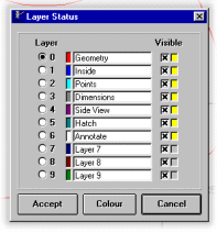
The Layers in CDL-V3 can be named, to help distinguish their functions. You can also associate a default colour to each layer if you wish. |
||
|
Browsing
In
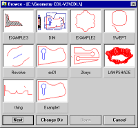
the file menu, BROWSE presents you with a pictorial menu of available drawing
files, so you never lose drawings because you forgot the filename.
|
 |
||
 |
Tool
Tips
Let the mouse hover over a screen item, and a short explanation of its purpose will pop-up to help you with the learning process. |
||
|
Font
Selection
You
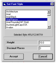
can take advantage of any font installed on the host computer for viewing
and printing Annotations.
Win2000
Help
The
extensive help in CDL-V3 is styled on the Win2000 model, with menu-style
navigation and hyperlinks to let you find what youíre looking for faster
than ever.
|
 |
||
|
While
Turning, roughing and facing operations can tackle horizontal and
vertical recesses.
|
Autofit
Whenever you create a new element that is outside the current field of view, Autofit can zoom the drawing scale to include the new element. A great time-saver. |
||
 |
CNC
NotePad Program Editor
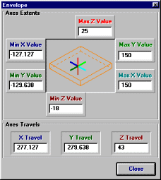
View Extents lets you see how much space the programmed part occupies without having to dry run the machine. The infinite file length capacity of CNC NotePad will handle program files as big as will fit in your computer for editing, re-numbering or global axis transformations. |
||
|
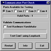
COM
Port Testing
Setting
up Comms can be a tricky business: with CNC Terminal Comms, you can save
hours of setup time by making sure youíre starting with a functioning port
and cable!
|
|